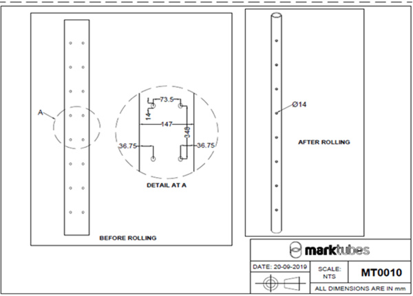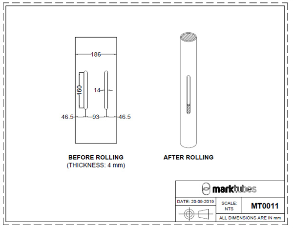
I. Profile Drawing: (Punching details as per given below)


II. Process Flow:
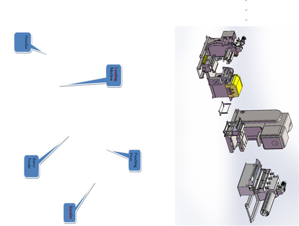
Uncoiler & Straightener ------ Servo Feeder ----- Punching Press ----- Recoiler
III. Main Component Data:
1. Uncoiler & Straightener : 1 set
2. Servo feeder : 1 set
3. Punching press : 1 set
4. Recoiler : 1 set
Main Parameter:
1. Speed : 20mm/min
2. Feeding times : 1m≤18 times/min/depending on customer's product
3. Feeding direction : as per buyer
4. Electrical basic parameters:
ü Power supply : as per buyer
ü Frequency : as per buyer
5. Basic air pressure parameters : 5 kg/cm2
6. Basic parameters of oil pressure : 7-10 kg/cm2
7. Suitable materials: CR,GI,Aluminium
8. Tensile strength <400Mpa; Yield strength <500Mpa
Straightening capacity chart:
| Material thickness (mm) | 0.5-2.2 | 2.5-3.5 | 4.0 |
| Material width (mm) | 300 | ||
IV. Uncoiler and Straightener :
| Model / Item | HBL-300 |
| Maximum overfeed width | 70mm-300mm |
| Maximum material thickness | 0.5-4.0mm |
| weight capacity | 4 Ton |
| Feeding speed | 16 m/min |
| Expansion range | Φ450mm-Φ530mm |
| Suitable for maximum coil outer diameter | Φ1500mm |
| Feed roller | Up 2/down 2 |
| Correction roller | Upper 4/lower 5 |
| Rack expansion method | Hydraulic |
| Rack motor | Oil motor drive |
| Leveling motor | 3kw |
| Loading trolley | No |
| Equipment color | As per buyer |
V. Servo feeder specifications:
| Model / Item | NCF-300 |
| Maximum overfeed width | ≤300mm |
| Maximum material thickness | 0.5mm-4.0mm |
| Feeding speed | 16m/min |
| Material feeding accuracy | ±0.3mm |
| Relaxation mode | Pneumatic |
| Stop adjustment width | 50mm-300mm |
| Feed servo motor | 2.9KW |
| Equipment color | As per buyer |
VI. Punching Press Specifications:
| Model/ Item | Type – JH21 – 125 | |
| Nominal Force | 1250 kN | |
| Nominal Stroke | 6 mm | |
| Slide Stroke | 160 mm | |
| Strokes Per Minute (SPM) | Fixed | 50 / min |
| Variable (Optional) | 40-60 /min | |
| Max die Height | 350 mm | |
| Die Height adjustment | 80 mm | |
| Between Slide Centre and frame | 350 mm | |
| Bolster Area [F.B * L.R] | 680 x 1150 mm | |
| Bolster thickness | 140 mm | |
| Bed Opening [Dia/ F.B * L.R] | 420 x 540 mm | |
| Slide Area [F.B * L.R] | 540 x 680 mm | |
| Shank Hole (Φ Dia x Depth) | Φ 60 x 80 mm | |
| Between Columns | 760 mm | |
| Main Motor Power | 11 kw | |
| Air Cushion (Option) | Air Bag type eject (Force x Stroke) | 110 kN x 80 mm |
| Cylinder type eject (Force x Stroke) | 60 kN x 90 mm | |
| Outline Dimension | 1850mm x 1490mm x 2950mm | |
| Net Weight | 9900 kgs [9.9 T] | |
VII. Recoiler Specification:
| Model/ Item | TC-300 |
| Maximum overfeed width | 70mm-300mm |
| Maximum material thickness | 0.5-4mm |
| Weight capacity | 4Ton |
| Feeding speed | 16m/min |
| Expansion range | Φ450mm-Φ530mm |
| Suitable for maximum coil outer diameter | Φ1500mm |
| Rack expansion method | Oil pressure tightening |
| Rack motor | Oil motor |
| Is there a tension device? | YES |
VIII. Standard function structure and optional configuration table:
| SNo. | Project | “●” is standard
“○” is optional configuration "-" is no configuration |
Description |
| 1 | Photoelectric material arc control method | ○ | Start with an inductive material arc length control device |
| 2 | Material rack hydraulic expansion | ● | Convenient to expand and contract the expansion range, improve production efficiency |
| 4 | Pressing arm device | ● | It helps the rack to run the bulk material and the material fixing belt, and the suburbs reduce the safety of the operators. |
| 5 | Feed arm device | ● | Helps material to leveler / next equipment feed |
| 6 | Roll loading trolley | ○ | Convenient material roll feeding to material rack |
| 7 | Material support shaft device | ● | Used for auxiliary material frame to support gravity |
| 8 | Crossing bridge buffering device | - | Used for leveling machine to feeder feeding material and material arc control |
| 9 | Material frame frequency control | ● | Change the speed of receiving and discharging materials |
| 10 | straightening machine frequency control | ● | Change the speed of the planer |
| 11 | straightening machine feeding and folding arm device | ● | Convenient material head enters the leveling machine |
| 12 | Leveling shaft back pressure roller | ○ | Used to support the leveling shaft to improve the leveling effect |
| 13 | Roller rubber on the leveling machine | ○ | Used for surface protection of materials |
| 14 | straightening machine discharge on the roller | ○ | Used for surface protection of materials |
| 15 | Roller rubber on the feeder | ○ | Used for surface protection of materials |
Technical Description:
1.Material rack
1) Function: Used to support the coil material discharge.
2) Main structure: Frame, expansion assembly, main shaft, press arm assembly, electric unit Fractional composition.
3) Rack: Welded by ordinary carbon steel plate and 100×100 square tube, tandem spindle and two bearing seats once welding to ensure that the spindle is concentric.
4) Expansion component: Expansion range diameter Φ450mm~Φ530mm, maximum width 300mm maximum. The diameter of the circle is Φ1500mm, and the four curved plates are slid-ably expanded by the square iron connection with the main shaft.
5) Spindle: It is processed by 45# round steel quenching and tempering car with a load of 4 tons.
6) Pressing material arm assembly: Feeding the auxiliary material to the leveling feeder with the elastic pressing material from the coil material auxiliary.
2. Straightening machine
1) Function: Used for leveling materials.
2) Main structure: Leveling roller, electric part, and feeding and hanging seat assembly.
3) Straigtening roller: It is processed by 40Cr round steel after quenching and tempering, and is processed by two times of electroplating and external grinding. The surface gloss has no trace and the hardness reaches above HRC 62 degrees. One of the lower flattening rollers is biased Heart roller.
4) Feeding roller: Pneumatically loosely feeds and leveling the shaft, and the turbine vortex is manually adjusted to adjust the leveling roller.
5) Inlet and outlet support: 7 plating drums, two sets of material wheel width 50mm-300mm。
3. Servo Feeder
1) Function: It is used for fixed length feeding.
2) Main structure: Feeding roller, electric part, feeding and discharging seat assembly.
3) Feeding roller: Feeding by the upper and lower roller shafts, the roller material is 40Cr round steel, and the processing is high. Frequency treatment, after two times of electroplating and external grinding, the surface gloss has no trace and the hardness reaches HRC62 degree the above.
4) Electric power: Driven by servo motor, pneumatically loose feed shaft.
5) Inlet and outlet support: 3 plating drums, two sets of material wheel width 50mm-300mm.
4. Recoiler
1) Function: Used to support the coil material receiving.
2) Main structure: Frame, expansion assembly, main shaft, electric part and so on.
3) Rack: Welded by ordinary carbon steel plate and 100×100 square tube, tandem spindle and two bearing seats once. Welding to ensure that the spindle is concentric.
4) Expansion component: Expansion range diameter Φ450mm~Φ530mm, maximum width 300mm maximum. The diameter of the circle is Φ1500mm, and the four curved plates are slid-ably expanded by the square iron connection with the main shaft.
5) Spindle: It is processed by 45# round steel quenching and tempering car with a load of 4 tons.
6) Electrical power: frequency converter speed regulation, 4.0KW motor with cycloidal pin reducer with belt drive。
Equipment structure and schematic diagram (this figure is for reference only):

| Raw Material | Type | Galvanized Sheet |
| Thickness | 0.4-4mm | |
| Performance | Speed | Max. 16m/min |
| Uncoiler | Type | Hydraulic |
| Capacity | 4 T | |
| Main Machine | Main Roller Station | 5 |
| Main Drive | Hydraulic Motor or Servo Motor | |
| Transmission Type | Chain | |
| Cutting | Cutter Type | Hydraulic |
| Cutter Material | Cr12 |